Cable harnesses are usually designed according to geometric and electrical requirements. A diagram is then provided (either on paper or on a monitor) for the assembly preparation and assembly.
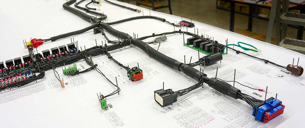
The wires are first cut to the desired length, usually using a special wire-cutting machine. The wires may also be printed on by a special machine during the cutting process or on a separate machine. After this, the ends of the wires are stripped to expose the metal (or core) of the wires, which are fitted with any required terminals or connector housings. The cables are assembled and clamped together on a special workbench, or onto a pin board (assembly board), according to the design specification, to form the cable harness. After fitting any protective sleeves, conduit, or extruded yarn, the harness is either fitted directly in the vehicle or shipped.
In spite of increasing automation, hand manufacture continues to be the primary method of cable harness production in general, due to the many different processes involved, such as:
- routing wires through sleeves,
- taping with fabric tape, in particular on branch outs from wire strands,
- crimping terminals onto wires, particularly for so-called multiple crimps(more than one wire into one terminal),
- inserting one sleeve into another,
- fastening strands with tape, clamps or cable ties.
It is difficult to automate these processes, with major suppliers still using manual means of production, only automating portions of the process. Manual production remains more cost effective than automation, especially with small batch sizes.
Pre-production can be automated in part. This affects:
- Cutting individual wires (cutting machine),
- crimping terminals onto one or both sides of the wire,
- partial plugging of wires prefitted with terminals into connector housings (module),
- soldering of wire ends (solder machine)
- twisting wires.
Testing the electrical functionality of a cable harness can be done with the aid of a test board. The circuit diagram data are pre-programmed into the test board, where harnesses can be tested individually or in multiple numbers.